30 September 2019

RGB LED Mapping: Color Selector


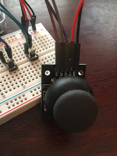
For this mapping exercise I decided to create an interactive color selector. Ideally the main goal is for the user to manipulate the first LED’s colors through the controllers and match the second LED’s color. Each of the controllers change the value of a single pin on the first LED. The potentiometer controls the red pin, the joystick controls the green pin, and the water sensor controls the blue pin. In addition to controlling colors, the joystick has a button that changes the second LED’s RGB values with random numbers within the color range (0-255). It also outputs a beep through the buzzer each time it is reset.


For now this color selector is simple, but ideally it could work as a game for the user to try and match the second LED’s color. If coded, the buzzer could work as a feedback to the user once they have successfully matched the color of the second LED. Also, if connected to a screen, the values of the first LED could be printed after the sound for the user to know exactly how the color is made and possibly save the combination for future use.


Mapping: Your Personal, Portable Therapist

For the mapping assignment, I focused on the questions: "Can we express a mood with a single pixel?" and "How can I incorporate a buzzer into this?"

How could I use the analog controls to express mood, and which controls would correlate with different emotions? Why would these correlations exist?

The thought of where to include a buzzer almost immediately made me think of a therapy session. The therapist (RGB LED) would show an emotional response via color to your actions as a patient (expressed via analog controls). Originally, I wanted to have it so that the buzzer would go off after a short time, ideally cutting the therapy interaction off in a surprising moment to (hopefully humorously) convey the idea that even though you may be making emotional progress and communicating well, it will end at a set time regardless of the actual experience of the session.

Here's a sketch of the idea:


I focused on the assignment requirements, so I wasn't able to spend too much time trying to figure out how to have a timer run in the background to trigger the buzzer while the code for interaction runs without delay. However, I did incorporate the buzzer idea in a different way - if you "cry" too much (measured by the water detection) the session will end.

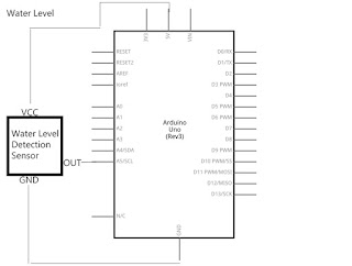
Here's the schematic and images of the setup:

Schematic
All the things
Wires on a breadboard

I do sometimes have a problem where the sound sensor code is trigger by the water sensor (and not because of the buzzer going off). It seems like the kind of issue that would be resolved with a decoupling capacitor as described in the readings. However, from the PDF paired with the kit, I believe there should be a capacitor in the sound sensor already. I did try adding one but it caused more problems so I took it out.

At the end, this was the result:


Code below:


Yours truly,
Toupee4

Mapping: It's Finicky

Getting the RGB LED to respond like I wanted was more difficult than I thought it would be. My original idea was to have this project be a interactive example on how our country ignore the science of climate change using the light sensor and water sensor. As I put everything together it all worked, but it didn't work the way I was hoping so I had to table the idea for another time. I believe my main issue was with the light sensor, but I didn't have the time to redo what I have put together.

The result of all of this is an LED light that can be manipulated in three different ways: light sensor, potentiometer, and water sensor. The potentiometer can also be used to activate the active buzzer after crossing a certain threshold. 

Materials:
  • 17 Jumper Wires
  • 1 Arduino UNO
  • 1 RGB LED
  • 3 220ohm resistors
  • 1 photoresistor
  • 1 Water Sensor
  • 1 Potentiometer
  • 1 active buzzer


Active Buzzer Schematic

LED Schematic

Potentiometer Schematic

Water Sensor Schematic


Original Sketch


29 September 2019

Mapping: Game On!


For this project, I decided to use three different controllers: potentiometer, photocell and the joystick. The potentiometer controls red on the RGB LED, the photocell controls green on the RGB LED and the joystick controls red and blue on the RGB LED.


I also implemented two buttons, an on and off button. Nothing happens when you press the first button (line 50 in the photo) but when you press the second button (line 55 in the photo) and you’re viewing the serial monitor the button shows how many times it’s pressed.


The potentiometer controls the brightness or dullness of the red light as the knob is turned.


The photocell allows the green light to shine brighter depending on the amount of light given to the photocell: the more light you give it the more the green light will appear, otherwise it goes back to the default color.


The joystick makes finding your primary colors like a game, you have to navigate your way to the red and the blue and discover the other colors along the way.


I couldn't draw all the schematics on one page, so I drew them separately. 


Colors Division


Mapping my RGB was the most challenging task so far! However, I came up with controlling each color (blue, red, green) using one alanolg controller to each color. The potentiometer controls green, the sound sensor controls blue, and finally, red is controlled by the photocell. I also used a button that only turns off the LED once it pressed. For this project, I tried to do other different ideas that would look much better than this one, but unfortunately, none of them worked!


Figure 1, Picture


Figure 2, Schematic


Figure 3, Sketch


Figure 4, Video 


Figure 5, Code

28 September 2019

Mapping: Poor Man's Nonfunctional Wired Air Pods

GOAL: Create an analog system for changing the color of a single RGB pixel.

OBJECTIVE: To practice mapping different ranges of values.

MATERIALS:

  • 20x Jumper Wires
  • 1x RGB LED
  • 3x 220ohm resistors
  • 1x Water Sensor
  • 1x Analog/Digital Joystick
  • 1x Pentiometer
  • 1x Passive Buzzer
  • 1x Elegoo UNO R3


Admittedly, I am less excited to type this up after my RGB LEDs burned my eyes out,
but let's get into it. ðŸŒˆðŸŒŸ

Mapping These Pods

So, thanks to a resurface of stale memes in my friend group, the really convoluted and obtuse narrative of my device intertwines with that of wired air pods-- or as we poor folk say, headphones. As such, I decided to include a joystick to simulate play controls, a pentiometer to simulate volume control, and a water sensor so as to protect one's bourgeoisie status. It's not remotely similar to an actual set of air pods, but it's what I kept in mind while designing this amalgamation.


Original Mockup
Uses colors to denote relationships and overall circuit flow

In my original plans, seen above, I decided to have different colors coordinated to different analog inputs. The water sensor uses red like an alarm. The joystick, outputting three values, is associated with two colors and the override mode. Lastly, the pentiometer, which controls volume, is paired with green so as not to be confused with other outputs.

Here's the result, though it's important to note some of the modules (joystick & water sensor) are off-screen due to wire limitations. I've also included the schematic, demonstration, and my code to better clarify the project's functionality. While I did have some further plans for the buzzer and joystick-- namely the joystick controlling pitch or acting like next/previous-- too many attempts at failed debugging have pushed those plans to a later, more zen-ful date.


I don't know if you can hear my
lack of caffeine, but I sure can.


  1
  2
  3
  4
  5
  6
  7
  8
  9
 10
 11
 12
 13
 14
 15
 16
 17
 18
 19
 20
 21
 22
 23
 24
 25
 26
 27
 28
 29
 30
 31
 32
 33
 34
 35
 36
 37
 38
 39
 40
 41
 42
 43
 44
 45
 46
 47
 48
 49
 50
 51
 52
 53
 54
 55
 56
 57
 58
 59
 60
 61
 62
 63
 64
 65
 66
 67
 68
 69
 70
 71
 72
 73
 74
 75
 76
 77
 78
 79
 80
 81
 82
 83
 84
 85
 86
 87
 88
 89
 90
 91
 92
 93
 94
 95
 96
 97
 98
 99
100
101
102
103
104
105
106
107
108
109
110
111
112
113
114
115
116
117
118
119
120
121
122
123
124
/*************************************************
 * Pins
 *************************************************/

// Defining Pitches

// LED, PWM

const int blueDude = 3;
const int greenDude = 5;
const int redDude = 6;
int index = 0;
int alert = 10;
int fade = 10;

// Speaker, PWM

const int speakerBoy = 11;
int speakerToggle = 0;

// Joystick

const int rollingGirl = 12;
const int rollingX = A1;
const int rollingY = A0;
int buttonToggle = 0;

// Pentiometer

const int twirlyBoy = A3;

// Water Sensor

const int waterBoy = A5;

/*************************************************
 * Setup
 *************************************************/

void setup() {
  // Outputs
  pinMode(redDude, OUTPUT);
  pinMode(blueDude, OUTPUT);
  pinMode(greenDude, OUTPUT);
  pinMode(speakerBoy, OUTPUT);
  digitalWrite(speakerBoy, LOW);

  // Inputs
  pinMode(rollingGirl, INPUT);
  digitalWrite(rollingGirl, HIGH);
  
  Serial.begin(9600);
}

/*************************************************
 * Loop
 *************************************************/

void loop() {
  delay(50);  

  // GATHER INPUTS
  
  // Check Inputs and obtain values
  // joystick, pentiometer, water sensor
  // TwirlVolume: use pentiometer to set buzzer volume
  int buttonState = digitalRead(rollingGirl);
  int xState = analogRead(rollingX);
  int yState = analogRead(rollingY);
  int twirlyValue = analogRead(twirlyBoy);
  int twirlVolume = twirlyValue * (5.0/1023.0);
  int waterValue = analogRead(waterBoy);

  // MAP VALUES
  
  int rollingMapX = map(xState, 0, 1024, 0, 255);
  int rollingMapY = map(yState, 0, 1024, 0, 255);
  int twirlyMap = map(twirlyValue, 0, 1023, 0, 255);
  int waterMap = map(waterValue, 0, 1023, 0, 255);

  // TOGGLE
  // Button and toggle are controlled by joystick press
  // If button is pressed, handle toggle accordingly
  if (buttonState == 0) {
    if (buttonToggle == 0) {
      buttonToggle++;
    } else { 
      buttonToggle--; 
    }
  }

  // SEQUENCES
  // First: Check if toggle is set; if not, continue with sequences
  // Second: Check if rich airpods are wet, flash alarm so as not to become poor
  // General sequence: map red/blue to joystick, and green to pentiometer
  // Finally, if toggle was set, disable rest of sequences

  if (buttonToggle == 0){
    // Flash LED like alert if water sensor trips
    if (waterMap >= 20) {
      analogWrite(blueDude, LOW);
      analogWrite(greenDude, LOW);
      analogWrite(redDude, index);
      index = index + alert;
      if (index <= 0 || index >= 250) {
        alert = -alert;
      }
    // General map to joystick and pentiometer
    } else {
      analogWrite(blueDude, rollingMapX);
      analogWrite(redDude, rollingMapY);
      analogWrite(greenDude, twirlyMap);
      analogWrite(speakerBoy, twirlVolume);
    }
  // Override Sequence
  } else {
      for (int x = 255; x > 0; x--) {
        analogWrite(redDude, x * -1);
        analogWrite(blueDude, x * 5);
        analogWrite(greenDude, x * 2);
        delay(50);
      }
  }
}

23 September 2019

Multi Switch: Turn on the lights


For this multi meter I decided to create an interactive logic game. The main goal is to find a way to have all the lights turned on at the same time. Each button has a set of conditionals that turn some of the LEDs on or off. The 3 LEDs receive their power from the Arduino, which also receives the input from the buttons when they are pressed. Through exploration or logic, the user can find a way to solve the puzzle while pressing the buttons in a specific order. This game can be expanded with many more lights, making it even harder to solve each time.


It Doesn't Work

This project was a grand (mis)adventure. First, I attempted to create what is known as a "Lights Out" puzzle, where all lights are on in a grid and you need to turn them all off. Pushing a button/light turns that one off and causes a state change to those adjacent to it. So, if they are on they'll turn off and if they are already off they'll infuriatingly turn on. I thought, "Hey, I've always wanted to know how to do this, I'll give it a try! It will probably be a little challenging, but it's basically just coding state changes so I kinda know the objective!" Here's a basic sketch of what I had in mind:

This is basically how the game works - the rules are easy but success is difficult and usually involves a lot of guesswork........

After several attempts at wiring and fitting a 3x3 grid of LEDs and corresponding buttons on the board, I realized I had made a major oversight: how was I going to individually program 18 components with the 13 pins of an Arduino?? I didn't know how to get the Arduino to recognize individual LEDs on a string attached to one data pin, which was rather essential. Also, it was kind of a mess at this point anyway.

Feeling only a moderate amount of discouragement, I decided to try to make a different game: Simon Says. Series of colors lights up, push the corresponding buttons in order. I thought, "This will be so much easier! I can just use a few LEDs, create a sequence, then track when the correct buttons are pushed!" If you're wondering how I'm going to do that last part, you probably know what's going to happen later.

Here's a simple sketch of my simple idea that definitely wouldn't be too complicated to make:

Simple mockup of LED and button sequences for victory


Ultimately I ended up adding a "start" button that triggers the sequence and game. I did not add a "victory" light for... reasons (you'll see). I placed everything on the breadboard like so:

Arrangement on breadboard

Schematic

I wanted to keep the board clean looking and leave space for people to push the buttons and clearly see the lights (aaaand limit the mess I had made at this point with the accumulating pile of difficult-to-read resistors) so I used "INPUT_PULLUP" instead of putting resistors between the buttons and pins.

For the code, I set up a variable called "score" and used a series of "if/else" statements to try to track correct button pushes. If incorrect, all the lights would flash and the game would reset. The problem is, for some reason I have yet to understand, "score" was not registering, so any button push triggered the reset state. I Googled and experimented and tested and isolated code to make sure it did what I wanted, all to no avail.

In the end, my frustration led me to the final version of the game: you can try playing Simon Says, but the buttons don't do what you want. Enjoy!


Here's the code I ended up using, including the remnants of the original "score" code I couldn't get to work.


Emergency Cooling System

The hot Florida days takes it's toll on everyone. If only there was some way we could stay cool on the go. Now we can! Thanks to the Emergency Cooling System. It's easy, all you need is:

1 Arduino Uno
1 breadboard
3 LED
4 buttons
2 220 resistors
1 1k resistor
3 10k resistors
16 jumper wires
1 fan

Just engage each of the three phases and the Emergency Cooling system is ready to go!

Each button turns on a corresponding LED, once each LED is turned on the cooling system is warmed up and ready to launch.
For some reason I find ridiculous solutions to simple problems hilarious, so I thought surly this has to be the most absurd way for someone to cool themselves off. Originally I planned for a very robotic voice to announce each phase that is activated but I don't believe our kits came with an SD card reader so the Arduino could play the audio files over a speaker. As a stand in, I added the voice to the uploaded video.

Photo of completed multi-switch

Initial Sketch
Schematic

On and Off Switch


For this project, I went with a simple on and off switch. I used 4 buttons to make two on and off switches. I used one pair to turn the blue LED on and off when pressed. I used the other pair to turn the white LED on and off and make the red LED blink when I turned off the white LED. The blue and white LEDs are connected with 1k resistors and the red LED is connected with the 330 resistor. After reading the lesson on digital inputs, I decided to follow the diagram in the lesson and not use the extra resisitors.

Materials Used:

1 Arduino
3 LED lights: Red, White and Blue
4 Buttons
1 USB connector
15 jumper wires
2 1k resistors
1 330 resistor


22 September 2019

The LEDs' race

For this project, I used 15 LEDs, 5 of each color (blue, white, and green). Every 3 LEDs (one from each color) are organized in a series row and connected to one resistor of 220 ohms. There are three buttons and each of which is connected to a 10K resistor. The switches are programmed to turn on the sequences in three different ways. The first button turns on the lights starting from bottom to top, and the second button does the opposite of that, it turns on the series from top to bottom. The last button randomly turns on the sequences.


Figure 1 - A picture of the work


Figure 2 -  Schematic of the board


Figure 3 - A sketch of the wiring 


Figure 4 - Video of how it works

Figure 5 - Code Blocks of the used coding

21 September 2019

Multi Switch : Making Music

GOAL: Design a system to control multiple LEDs with switches and code.

OBJECTIVES: Practice fundamental coding for Arduino using digital inputs and outputs.

MATERIALS USED:
  • 3 LEDs
  • 3 Switches / buttons
  • 3 Resistors appropriate to the LEDs
  • 3 Resistors appropriate to the buttons/switches
  • 1 Arduino
  • 1 Breadboard
  • 13 Jumper wires
  • 1 Passive Buzzer (It might be active, honestly, I forgot)


Playin' Music

Like most people, I like music.
Honestly, I'm not sure who doesn't, but I guess they're out there (y'all are weirdos though).

Anyway, thanks to this affinity and my impatience to get to other components in the elegoo box, I decided to create a makeshift sound board. Or, after I discovered it's a little hard to play more than two tones simultaneously, a makeshift music box. Set on this idea, I began to hash it out using good old fashion doodling:

Demonstrating connections through
an unintentional Powerpuff Girl motif

Messy, but a start. 

In the beginning, I knew that I wanted each button to correspond to an LED and, in turn, have a specific impact on the speaker. So, logically, a button would be pressed and, using a conditional, the code would fire off a song sequence and light up an LED. The building process itself took this idea, refined it several times, and expanded on it by adding a toggle state to the final button. By doing so, each button plays a song-- except the third, which actually plays *drum roll* two!

Here's a look at the result:


Step aside Marble Soda, there's a new mash up in town

The sound board uses seven pins total to connect the main acting components. I also tried to set it up a little more ergonomically; as a result, some of the wires are color coded, and the placement of each button correlates with the placement of an LED. In other words, the furthest left button generally lights the furthest left LED.

To further refine this design, I also attempted (keyword, here) to create a schematic and code that are like-wise easy to view or understand. These renditions can be seen below:

Pin-wise: the speaker was 3, the LEDs were 5-7, and the buttons were 8-10,
though I wasn't quite sure how to communicate this yet.

(Note: the pitches.h file is the same used here.)

  1
  2
  3
  4
  5
  6
  7
  8
  9
 10
 11
 12
 13
 14
 15
 16
 17
 18
 19
 20
 21
 22
 23
 24
 25
 26
 27
 28
 29
 30
 31
 32
 33
 34
 35
 36
 37
 38
 39
 40
 41
 42
 43
 44
 45
 46
 47
 48
 49
 50
 51
 52
 53
 54
 55
 56
 57
 58
 59
 60
 61
 62
 63
 64
 65
 66
 67
 68
 69
 70
 71
 72
 73
 74
 75
 76
 77
 78
 79
 80
 81
 82
 83
 84
 85
 86
 87
 88
 89
 90
 91
 92
 93
 94
 95
 96
 97
 98
 99
100
101
102
103
104
105
106
107
108
109
110
111
112
113
114
115
116
117
118
119
120
121
122
123
124
125
126
127
128
129
130
131
132
133
134
135
136
137
138
139
140
141
142
143
144
145
146
147
148
149
150
151
152
153
154
155
156
157
158
159
160
161
162
163
164
165
166
167
168
169
170
171
172
173
#include "pitches.h"

// Firstly: Thanks @ Arduino toneMelody() tutorial

/*************************************************
 * Songs and Tempos
 *************************************************/

// Left non-const because I want to try changing these via button in the future.
// Song tempos may not be totally accurate because I made these by ear.

int zeldasSong[] = {
  NOTE_E4, NOTE_G4, NOTE_D4, NOTE_C4, NOTE_D4, NOTE_E4, NOTE_G4, NOTE_D4
};

int sariasSong[] = {
  NOTE_F4, NOTE_A4, NOTE_B4, NOTE_F4, NOTE_A4, NOTE_B4,
  NOTE_F4, NOTE_A4, NOTE_B4, NOTE_E5, NOTE_D5
};

int eponasSong[] {
  NOTE_D5, NOTE_B4, NOTE_A4, R, NOTE_D5, NOTE_B4, NOTE_A4, R,
  NOTE_D5, NOTE_B4, NOTE_A4, NOTE_B4, NOTE_A4
};

int marioSong[] = {
  NOTE_E4, NOTE_E4, NOTE_E4,
  NOTE_C4, NOTE_E4, NOTE_G4, R, NOTE_G3
};

int zeldaTempo[] = {
  2,4,2,8,8,2,4,2
};

int sariaTempo[] = {
  8,8,4,8,8,4,8,8,8,8,4
};

int eponaTempo[] {
  3,5,1,12,3,5,1,12,3,5,2,2,1
};

int marioTempo[] = {
  8,4,4,8,4,3,6,3
};

/*************************************************
 * Pins
 *************************************************/
// These are a bit more organic as that's how I've best memorized variables in past. 
// Speaker

const int speakerBoy = 3;

// LEDs

const int blueDude = 5;
const int greenDude = 6;
const int redDude = 7;

// Buttons

const int blueHome = 8;
const int greenHome = 9;
const int redHome = 10;
int redToggle = 0;

/*************************************************
 * Setup
 *************************************************/

void setup() {
  // setting up pins
  pinMode(speakerBoy, OUTPUT);
  
  pinMode(blueDude, OUTPUT);
  pinMode(redDude, OUTPUT);
  pinMode(greenDude, OUTPUT);

  pinMode(blueHome,INPUT);
  pinMode(greenHome,INPUT);
  pinMode(redHome,INPUT);

  // this is just for aesthetics
  delay(500);                     
  digitalWrite(greenDude, HIGH);   
  delay(500); 
  digitalWrite(redDude, HIGH);
  delay(500);
  
  digitalWrite(blueDude, LOW);
  digitalWrite(greenDude, LOW);
  digitalWrite(redDude, LOW);

  // Serial.begin(9600);
}

/*************************************************
 * Loop
 *************************************************/

void loop() {
  // assign variables based on button state
  
  int blueState = digitalRead(blueHome);
  int greenState = digitalRead(greenHome);
  int redState = digitalRead(redHome);

  // FIRST: first button, first song, blue LED
  // If button is pressed, light LED and play song
  // Otherwise, turn off LED when song ends
  
  if (blueState == HIGH) {
    digitalWrite(blueDude, HIGH);
    // first melody
    // run through lullaby while changing note and duration
    for (int thisNote = 0; thisNote < 8; thisNote++) {
      int noteDuration = 1000/zeldaTempo[thisNote];
      tone(speakerBoy, zeldasSong[thisNote], noteDuration);
      int notePause = noteDuration * 1.30;
      delay(notePause);
    } 
  } else {
    digitalWrite(blueDude, LOW);
  }

  // SECOND: second button, second song, green LED
  
  if (greenState == HIGH) {
    digitalWrite(greenDude, HIGH);
    // second melody
    for (int thisNote = 0; thisNote < 11; thisNote++) {
      int noteDuration = 1000/sariaTempo[thisNote];
      tone(speakerBoy, sariasSong[thisNote], noteDuration);
      int notePause = noteDuration * 1.30;
      delay(notePause);
    }
  } else {
    digitalWrite(greenDude, LOW);
  }

  // THIRD: Third button, last two songs, mix of LEDs :^)
  // Uses a toggle based on 'red' button state for a bit more complexity
  // If button is pressed, first check toggle to decide what LEDs and song to run
  
  if (redState == HIGH) {
      if (redToggle == 0) {
      digitalWrite(redDude, HIGH);
      redToggle++;
      // third melody
        for (int thisNote = 0; thisNote < 13; thisNote++) {
          int noteDuration = 1000/eponaTempo[thisNote];
          tone(speakerBoy, eponasSong[thisNote], noteDuration);
          int notePause = noteDuration * 1.30;
          delay(notePause);
         }
      } else {
        // third alt melody
        digitalWrite(redDude, HIGH);
        digitalWrite(blueDude, HIGH);
        redToggle = 0;
        for (int thisNote = 0; thisNote < 8; thisNote++) {
          int noteDuration = 1000/marioTempo[thisNote];
          tone(speakerBoy, marioSong[thisNote], noteDuration);
          int notePause = noteDuration * 1.30;
          delay(notePause);
        }
      }
  } else {
    digitalWrite(redDude, LOW);
    digitalWrite(blueDude, LOW);
  }
}