For this project, I decided to use three different controllers: potentiometer, photocell and the joystick. The potentiometer controls red on the RGB LED, the photocell controls green on the RGB LED and the joystick controls red and blue on the RGB LED.
The potentiometer controls the brightness or dullness of the red light as the knob is turned.
The photocell allows the green light to shine brighter depending on the amount of light given to the photocell: the more light you give it the more the green light will appear, otherwise it goes back to the default color.
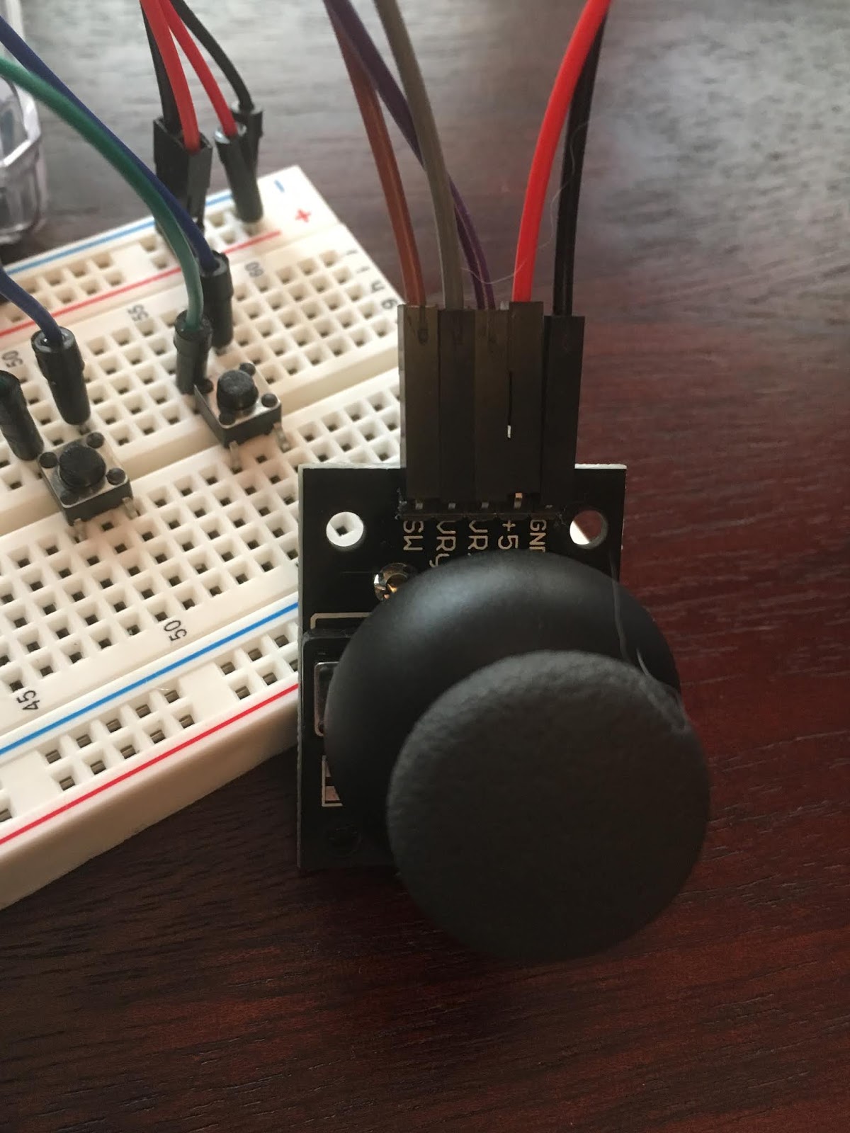
The joystick makes finding your primary colors like a game, you have to navigate your way to the red and the blue and discover the other colors along the way.
I couldn't draw all the schematics on one page, so I drew them separately.
This file contains bidirectional Unicode text that may be interpreted or compiled differently than what appears below. To review, open the file in an editor that reveals hidden Unicode characters.
Learn more about bidirectional Unicode characters
//Buttons | |
const int onButton= 10; | |
const int offButton = 9; | |
int index = 0; | |
int multiplier = 5; | |
int minVal = 500; | |
int maxVal = 500; | |
int ledPin = 13; // LED on Pin 13 of Arduino | |
int oldState = 1; | |
int temp = 1; | |
int clickCount = 0; | |
// Arduino pin numbers | |
const int SW_pin = 2; // digital pin connected to switch output | |
const int X_pin = 0; // analog pin connected to X output | |
const int Y_pin = 1; // analog pin connected to Y output | |
// Define Pins | |
#define BLUE 3 | |
#define GREEN 5 | |
#define RED 6 | |
void setup() | |
{ | |
pinMode(RED, OUTPUT); | |
pinMode(GREEN, OUTPUT); | |
pinMode(BLUE, OUTPUT); | |
pinMode(ledPin, OUTPUT); | |
pinMode(onButton, INPUT_PULLUP); | |
pinMode(offButton, INPUT_PULLUP); | |
pinMode(SW_pin, INPUT); | |
digitalWrite(SW_pin, HIGH); | |
Serial.begin(9600); | |
delay(1000); | |
} | |
// define variables | |
int redValue; | |
int greenValue; | |
int blueValue; | |
void loop() | |
{ | |
// wait for a second | |
int btnState = digitalRead(onButton); | |
Serial.print(btnState); | |
if (btnState == 0 && oldState == 1) | |
clickCount++; //clickCount = clickCount +1 | |
{ | |
Serial.print("Button clicked "); | |
// println(temp); | |
Serial.print(clickCount); | |
Serial.println(" times."); | |
} | |
if (digitalRead(onButton) == LOW) | |
{ | |
digitalWrite(ledPin, HIGH); | |
} | |
if (digitalRead(offButton) == LOW) | |
{ | |
digitalWrite(ledPin, LOW); | |
} | |
if(temp = 0){ | |
digitalWrite(ledPin, LOW); | |
temp = 1; | |
} | |
else { | |
digitalWrite(ledPin, HIGH); | |
temp = 0; | |
} | |
/* | |
#define delayTime 10 // fading time between colors | |
redValue = 255; // choose a value between 1 and 255 to change the color. | |
greenValue = 0; | |
blueValue = 0; | |
// analogWrite(RED, 0); | |
// delay(1000); | |
for(int i = 0; i < 255; i += 1) // fades out red bring green full when i=255 | |
{ | |
redValue -= 1; | |
greenValue += 1; | |
// analogWrite(RED, 255 - redValue); | |
// analogWrite(GREEN, 255 - greenValue); | |
analogWrite(RED, redValue); | |
analogWrite(GREEN, greenValue); | |
delay(delayTime); | |
} | |
redValue = 0; | |
greenValue = 255; | |
blueValue = 0; | |
for(int i = 0; i < 255; i += 1) // fades out green bring blue full when i=255 | |
{ | |
greenValue -= 1; | |
blueValue += 1; | |
// analogWrite(GREEN, 255 - greenValue); | |
// analogWrite(BLUE, 255 - blueValue); | |
analogWrite(GREEN, greenValue); | |
analogWrite(BLUE, blueValue); | |
delay(delayTime); | |
} | |
redValue = 0; | |
greenValue = 0; | |
blueValue = 255; | |
for(int i = 0; i < 255; i += 1) // fades out blue bring red full when i=255 | |
{ | |
blueValue -= 1; | |
redValue += 1; | |
// analogWrite(BLUE, 255 - blueValue); | |
// analogWrite(RED, 255 - redValue); | |
analogWrite(BLUE, blueValue); | |
analogWrite(RED, redValue); | |
delay(delayTime); | |
} | |
*/ | |
int potVal = analogRead(A0); | |
delay(1); //helps to do this because arduino one has one ADC chip that it switches between | |
Serial.print(potVal); | |
Serial.print("potVal: "); | |
int photoVal = analogRead(A2); | |
Serial.print(photoVal); | |
Serial.print("photoVal: "); | |
int joystickVal = analogRead(A4); | |
Serial.print(joystickVal); | |
Serial.print("joystickVal: "); | |
int joystickVal2 = analogRead(A5); | |
Serial.print(joystickVal2); | |
Serial.print("joystickVal2: "); | |
int mappedVal = map(potVal, minVal, maxVal, 0, 255); //take this number witht the range and convert it to this range | |
analogWrite(RED, mappedVal); | |
Serial.print(mappedVal); | |
Serial.print("mappedVal: "); | |
int mappedVal2 = map(photoVal, minVal, maxVal, 0, 255); //take this number witht the range and convert it to this range | |
analogWrite(GREEN, mappedVal2); | |
Serial.print(mappedVal2); | |
Serial.print("mappedVal2: "); | |
int mappedVal3 = map(joystickVal, minVal, maxVal, 0, 255); //take this number witht the range and convert it to this range | |
analogWrite(BLUE, mappedVal3); | |
Serial.print(mappedVal3); | |
Serial.print("mappedVal3: "); | |
int mappedVal4 = map(joystickVal2, minVal, maxVal, 0, 255); //take this number witht the range and convert it to this range | |
analogWrite(RED, mappedVal4); | |
Serial.print(mappedVal4); | |
Serial.print("mappedVal4: "); | |
Serial.print(minVal); | |
Serial.print("minVal: "); | |
Serial.print(maxVal); | |
Serial.println("maxVal: "); | |
Serial.print("Switch: "); | |
Serial.print(digitalRead(SW_pin)); | |
Serial.print("\n"); | |
Serial.print("X-axis: "); | |
Serial.print(analogRead(X_pin)); | |
Serial.print("\n"); | |
Serial.print("Y-axis: "); | |
Serial.println(analogRead(Y_pin)); | |
Serial.print("\n\n"); | |
delay(500); | |
} |
No comments:
Post a Comment
Note: Only a member of this blog may post a comment.